Author: | |
Department: | |
Created Date: |
2012-10-22 |
Reviewer: | |
Department: | |
Model Created Date: |
2012-10-22 |
Reviewer Comments: |
This is where to put your Executive summary.
So, replace this text with your overall Project Description.
Analysis Type -
Static Stress with Linear Material Models
Units -
Custom - (kN, m, s, °C, K, V, ohm, A, J)
Model location -
C:\Users\JPS\Documents\Algor\Rama4.fem
Design scenario description -
Design Scenario # 1
Static Stress with Linear Material Models may have multiple load cases. This allows a model to be analyzed with multiple loads while solving the equations a single time. The following is a list of load case multipliers that were analyzed with this model.
| Load Case | Pressure/Surface Forces | Gravity/Acceleration | Angular Velocity (Omega) | Angular Acceleration (Alpha) | Displacement | Thermal | Electrical |
|---|---|---|---|---|---|---|---|
| 1 | 1 | 1 | 0 | 0 | 1 | 0 | 0 |
The following lists the values used if acceleration or gravity was included in the analysis. The Acceleration/Gravity direction multiplier is multiplied by the Acceleration Due To Body Force which is then multiplied by the Acceleration/Gravity load case multiplier.
Acceleration Due To Body Force = 9 m/s²
| Acceleration/Gravity X Multiplier | Acceleration/Gravity Y Multiplier | Acceleration/Gravity Z Multiplier |
|---|---|---|
| 0 | 0 | -1 |
| Default Nodal Temperature | 0 °C |
| Source of Initial Nodal Temperatures | Model file |
| Time step from Heat Transfer Analysis | Last |
| Default nodal voltage | 0 V |
| Source of nodal voltages | Model file |
| Type of Solver | Automatic |
| Disable Calculation and Output of Strains | No |
| Calculate Reaction Forces | Yes |
| Invoke Banded Solver | Yes |
| Avoid Bandwidth Minimization | No |
| Stop After Stiffness Calculations | No |
| Displacement Data in Output File | No |
| Stress Data in Output File | No |
| Equation Numbers Data in Output File | No |
| Element Input Data in Output File | No |
| Nodal Input Data in Output File | No |
| Centrifugal Load Data in Output File | No |
| Part ID | Part Name | Element Type | Material Name |
|---|---|---|---|
| 1 | Rama stalowa | Beam | AISI E 52100 Steel |
| Element Type | Beam |
| Stress Free Reference Temperature | 0 °C |
| Layer 1 - Area | 0 |
| Layer 1 - SA2 | 0 |
| Layer 1 - SA3 | 0 |
| Layer 1 - J1 | 3 |
| Layer 1 - I2 | 1 |
| Layer 1 - I3 | 0 |
| Layer 1 - S2 | 0 |
| Layer 1 - S3 | 0 |
| Layer 2 - Area | 0 |
| Layer 2 - SA2 | 0 |
| Layer 2 - SA3 | 0 |
| Layer 2 - J1 | 3 |
| Layer 2 - I2 | 1 |
| Layer 2 - I3 | 0 |
| Layer 2 - S2 | 0 |
| Layer 2 - S3 | 0 |
| Layer 3 - Area | 0 |
| Layer 3 - SA2 | 0 |
| Layer 3 - SA3 | 0 |
| Layer 3 - J1 | 1 |
| Layer 3 - I2 | 8 |
| Layer 3 - I3 | 9 |
| Layer 3 - S2 | 0 |
| Layer 3 - S3 | 0 |
| Layer 4 - Area | 0 |
| Layer 4 - SA2 | 0 |
| Layer 4 - SA3 | 0 |
| Layer 4 - J1 | 1 |
| Layer 4 - I2 | 8 |
| Layer 4 - I3 | 0 |
| Layer 4 - S2 | 9 |
| Layer 4 - S3 | 0 |
| Layer 5 - Area | 0 |
| Layer 5 - SA2 | 0 |
| Layer 5 - SA3 | 0 |
| Layer 5 - J1 | 2 |
| Layer 5 - I2 | 9 |
| Layer 5 - I3 | 2 |
| Layer 5 - S2 | 1 |
| Layer 5 - S3 | 0 |
| Layer 6 - Area | 0 |
| Layer 6 - SA2 | 0 |
| Layer 6 - SA3 | 0 |
| Layer 6 - J1 | 2 |
| Layer 6 - I2 | 9 |
| Layer 6 - I3 | 2 |
| Layer 6 - S2 | 1 |
| Layer 6 - S3 | 0 |
| Layer 7 - Area | 0 |
| Layer 7 - SA2 | 0 |
| Layer 7 - SA3 | 0 |
| Layer 7 - J1 | 1 |
| Layer 7 - I2 | 8 |
| Layer 7 - I3 | 9 |
| Layer 7 - S2 | 0 |
| Layer 7 - S3 | 0 |
| Material Model | Standard |
| Material Source | Autodesk Simulation Material Library |
| Material Source File | C:\Program Files\Autodesk\Simulation 2013\matlibs\algormat.mlb |
| Date Last Updated | 2004/10/28-16:02:00 |
| Material Description | None |
| Mass Density | 7 kN·s²/m/m³ |
| Modulus of Elasticity | 210000000 kN/m² |
| Poisson's Ratio | 0.3 |
| Thermal Coefficient of Expansion | 0 1/°C |
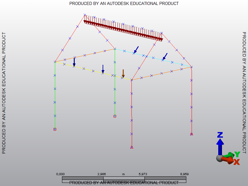
| ID | Description | Line ID | Element ID | Magnitude-I (N/m) | Vx-I | Vy-I | Vz-I | Magnitude-J (N/m) | Vx-J | Vy-J | Vz-J | A | B |
|---|---|---|---|---|---|---|---|---|---|---|---|---|---|
| 1 | Unnamed | 50 | 37 | 5,000000 | 0,000000 | 0,000000 | -1,000000 | 5,000000 | 0,000000 | 0,000000 | -1,000000 | 0,000000 | 1,000000 |
| 2 | Unnamed | 51 | 38 | 5,000000 | 0,000000 | 0,000000 | -1,000000 | 5,000000 | 0,000000 | 0,000000 | -1,000000 | 0,000000 | 1,000000 |
| 3 | Unnamed | 52 | 39 | 5,000000 | 0,000000 | 0,000000 | -1,000000 | 5,000000 | 0,000000 | 0,000000 | -1,000000 | 0,000000 | 1,000000 |
| 4 | Unnamed | 53 | 40 | 5,000000 | 0,000000 | 0,000000 | -1,000000 | 5,000000 | 0,000000 | 0,000000 | -1,000000 | 0,000000 | 1,000000 |
| 5 | Unnamed | 54 | 41 | 5,000000 | 0,000000 | 0,000000 | -1,000000 | 5,000000 | 0,000000 | 0,000000 | -1,000000 | 0,000000 | 1,000000 |
| 6 | Unnamed | 55 | 42 | 5,000000 | 0,000000 | 0,000000 | -1,000000 | 5,000000 | 0,000000 | 0,000000 | -1,000000 | 0,000000 | 1,000000 |
| 7 | Unnamed | 56 | 43 | 5,000000 | 0,000000 | 0,000000 | -1,000000 | 5,000000 | 0,000000 | 0,000000 | -1,000000 | 0,000000 | 1,000000 |
| 8 | Unnamed | 57 | 44 | 5,000000 | 0,000000 | 0,000000 | -1,000000 | 5,000000 | 0,000000 | 0,000000 | -1,000000 | 0,000000 | 1,000000 |
| ID | Description | Vertex Number | Node Number | Magnitude (kN) | Vx | Vy | Vz | Load Case / Load Curve |
|---|---|---|---|---|---|---|---|---|
| 1 | Unnamed | 78 | 31 | 20,000000 | 0,000000 | 0,000000 | -1,000000 | 1 |
| 2 | Unnamed | 72 | 28 | 20,000000 | 0,000000 | 0,000000 | -1,000000 | 1 |
| ID | Description | Vertex Number | Node Number | Magnitude (kN) | Vx | Vy | Vz | Load Case / Load Curve |
|---|---|---|---|---|---|---|---|---|
| 3 | Unnamed | 87 | 35 | 15,000000 | 0,000000 | -1,000000 | -1,000000 | 1 |
| 4 | Unnamed | 93 | 38 | 15,000000 | 0,000000 | -1,000000 | -1,000000 | 1 |
| ID | Description | Vertex Number | Node Number | Tx | Ty | Tz | Rx | Ry | Rz |
|---|---|---|---|---|---|---|---|---|---|
| 1 | Unnamed | 40 | 12 | Yes | Yes | Yes | No | No | No |
| 2 | Unnamed | 50 | 17 | Yes | Yes | Yes | No | No | No |
| ID | Description | Vertex Number | Node Number | Tx | Ty | Tz | Rx | Ry | Rz |
|---|---|---|---|---|---|---|---|---|---|
| 3 | Unnamed | 30 | 7 | Yes | Yes | Yes | Yes | Yes | Yes |
| 4 | Unnamed | 60 | 22 | Yes | Yes | Yes | Yes | Yes | Yes |
Displacement |
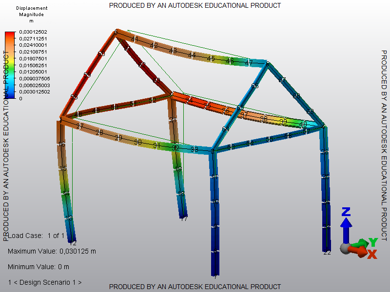
|